Personal insights and calculation guides from the world of structural engineering directly in your inbox.
The Simply Supported Beam - Ep. #7 Engineering Mechanics Series
|
Happy Wednesday, It’s already post #7 of the engineering mechanics series. So far we’ve covered the different static systems, static determinacy, types of loads on beams, and how to calculate reaction forces and internal forces. Today and in the next weeks, we’ll look more in detail at specific static systems and use all the knowledge we gained from the first #5 posts to perform hand calculations. Today, we’ll start with the most important static system in structural engineering - the simply supported beam.
Here’s what we’ll cover:
So let’s get into it. 🚀🚀 Real-life examples of simply supported beamsIt’s always good to know where and how these theoretical “models” are used in real-life, isn’t it? Here are 7 examples: 1.Precast concrete beams supported by precast columns 4. The wooden beams/panels of a bench are simply supported 5. Steel beam used for a door/window opening supported by masonry walls And there are so many more examples. Roughly 80% of the static systems I design as a structural engineer are simply supported beams. So knowing how to calculate the reaction and internal forces is crucial in structural engineering. Quick recap of the static systemWe’ve already shown the characteristics of the simply supported beam in earlier posts, but repetition is always good. And many new people have joined this newsletter since.
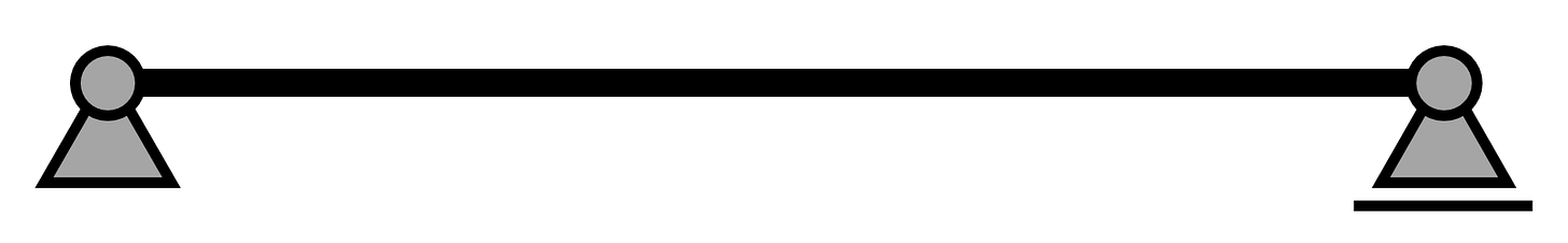
The simply supported beam is in most cases a horizontal beam having a roller and a pinned support on the ends. The beam can take normal and shear forces, as well as bending moments. It can be seen from the picture that the pinned support (a) takes up
The roller support (b) takes up
Examples of loading situationsLoads act on static systems. These loads result in reaction and internal forces such as bending moments, shear and normal forces. If there weren’t any loads acting on a static system, then the internal forces would also be 0. Line loadsLine loads on the simply supported beam are loads of the same value along a certain distance. An example is the self-weight/ dead load of a beam. If the beam is a timber beam, the line load is calculated as density * cross-sectional width * cross-sectional height.
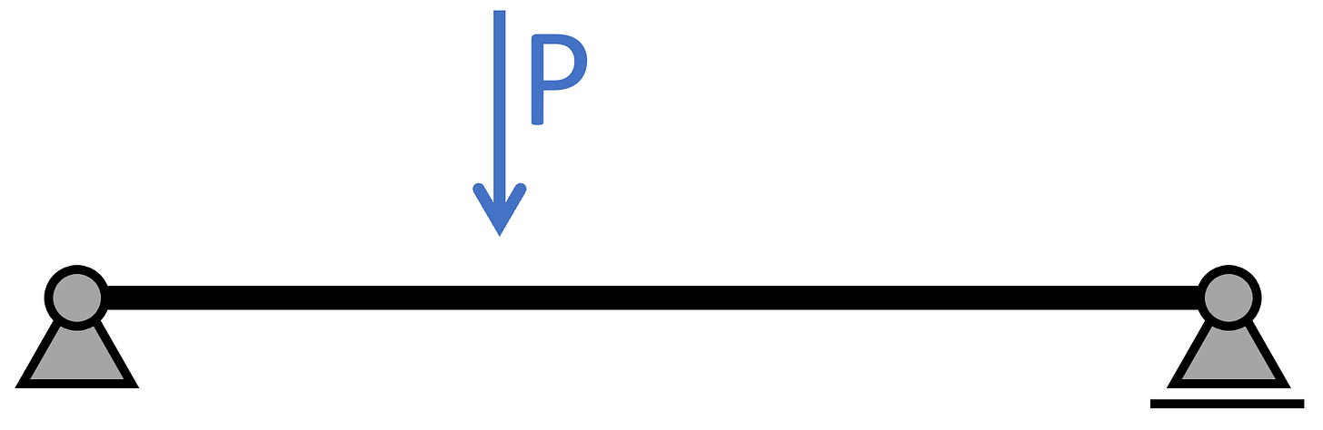
Other line loads could be the self-weight or live load of a hollow core slab, which is supported by a beam. Then the line load which is applied on the beam is calculated as density of the slab * thickness * span of slab / 2. Point loadsPoint loads are concentrated loads that are applied on the simply supported beam in one point.
An example could be a person’s weight like mine 😁😁 when sitting on a simply supported bench.
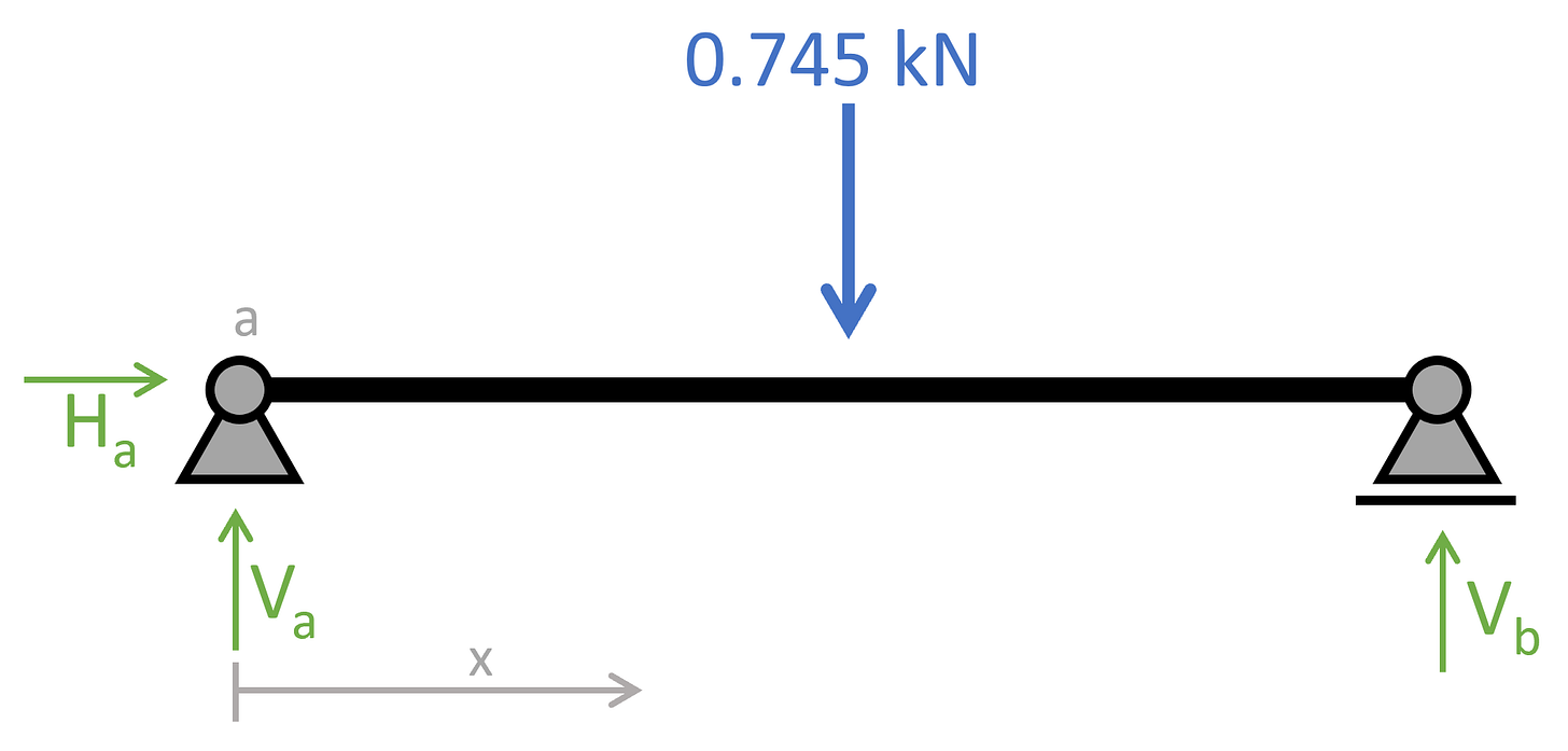
Now, there are more loads we could apply to a simply supported beam, like an external moment or a triangular line load. But line and point load are the most common. We finally get into the hand calculation. Example hand calculation of internal forcesLet’s use the example of the bench, which I am loading with my body weight. I currently weigh 76 kg. 🙄🙄 This leads to a point load of 0.745 kN to be very precise.
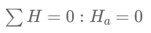
1. The first thing we always calculate in determinate structures are the reaction forces/moment. In our case, that is Ha, Va at support (a) and Vb at support (b) due to the equilibrium conditions.
2. Next, we calculate the shear forces and moments along the beam due to the reaction forces. The parameter x is introduced as the length between point a and any point on the beam.
3. The shear forces and bending moments can be calculated in dependence of x. Let’s make a first cut at a point between the support and the point load 0<x<1.0m.
As for the reaction force calculation, the equilibrium conditions are used to calculate the moment and shear forces at point x.
As we can see, the shear force is constant and not dependent on the parameter x. Let’s set x = 1.0m and see what results we get for the bending moment: In dependence of x and the Point load Q = 0.745kN a general formula for the bending moment of a simply supported beam for 0<x<l/2 can be formulated as:
You might have already come across the formula when we set x=l/2:
4. We now cut at a point between the point load and the endpoint 1.0m<x<2.0m.
The equilibrium conditions lead to:
5. Lastly, we can draw bending moment and shear force diagrams. The diagrams can be plotted by a tool like Excel using the formulas from above or drawn by hand. Or you can also create your own beam analysis program in Python. James O’Reilly shows step-by-step in his Substack guide how to analyse a simply supported beam in Python. I can recommend his newsletter if you want to get into Python. Shear force diagram – simply supported beam
Bending moment diagram – simply supported beam
ConclusionCalculating the internal forces repeatedly for different static systems is key to understanding the process and making less mistakes. The simply supported beam was the first example we looked at today. In the next weeks, we’ll look at more examples such as the cantilever beam, arches, trusses, etc. This was the 7th edition of the engineering mechanics series. See you next Wednesday for another post. Have a great rest of the week. Cheers, Laurin. ↓ Follow me on Social Media. ↓ |


Structural Basics
Personal insights and calculation guides from the world of structural engineering directly in your inbox.
Welcome back to the Structural Basics newsletter friends, Today, we'll cover the shear verification of bolted steel-to-timber connections. This type of connection can resist quite some loads as we'll see. But first, I wanted to briefly talk about 2 things: My 1st published podcast. I was invited by Daniel Dlubal to talk on the Dlubal podcast. Dlubal is one of the biggest international companies for finite element software. Some of you might know RFEM and RSTAB. They are one of my favourite FE...
Hello friends, Today, we'll cover the shear verification of screwed steel-to-timber connections. Let's get into it.. The 4 Steps To Calculate The Shear Capacity of Screws According To Eurocode In general we separate 2 types of shear connections in timber design: timber-timber connections and timber-steel connections We already covered all verification formulas of the different failure modes of EN 1995-1-1 (8.6), (8.7), (8.9)-(8.13) in episode #23. You can check out the episode here. In...
Hi friends, Today I want to show you a bracing system of a steel staircase which wasn't designed very well. I was the checking engineer of the project. In Germany there is a second engineering office for most projects checking the structural design / calculations. But the checking engineer only has to check the ULS verifications to make sure that the structure dosn't collapse. SLS checks such as deflections are not part of it. In the following pictures you can see that the columns are...